This website uses cookies to ensure you get the best experience on our website. Read our cookie policy


Apollo Orbis TimeSaver Diode Detector Base - ORB-DB-00003-APO

SKU
ORB-DB-00003-APO
£3.23 £2.69
Apollo Orbis TimeSaver Diode Detector Base - ORB-DB-00003-APO
- Buy 10 for £3.02 £2.52 each and save 6%
- Buy 20 for £3.00 £2.50 each and save 7%
- Buy 50 for £2.98 £2.48 each and save 8%
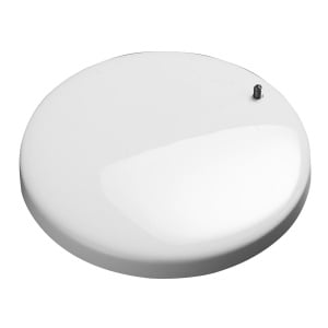
The TimeSaver® Diode Base has the same design as the standard TimeSaver® Base with the addition of a diode. It is used in systems which use active EOL monitoring for head removal.
The TimeSaver® Base is a design that provides installers with an open working area with fixing holes shaped to allow a fast mounting procedure.
Operation
Orbis has been designed to make installation fast and simple. The E-Z fit fixing holes are shaped to allow a simple three-step mounting procedure:
• Fit two screws to the mounting box or surface
• Place the Orbis base over the screws and slide home
• Tighten the screws
The base offers two fixing centres at 51 and 60mm.
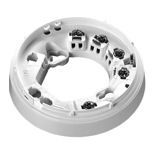
A guide on the base interior indicates the length of cable to be stripped. Five terminals are provided for the cables, four being grouped together for ease of termination.
The terminals are:
• positive IN
• positive OUT
• negative IN and OUT (common terminal)
• remote LED negative connection
• functional earth (screen)
The terminal screws are captive screws and will not fall out of the terminals. The base is supplied with the screws unscrewed in order to avoid unnecessary work for the installer.
The end-of-line resistor or active device should be connected between the OUT+ and COM– terminals.
If it is required that all detectors be fitted with their LEDs facing the same direction the bases must be fitted to the ceiling observing the marking on the exterior which indicates the position of the LED.
In many installations bases with diodes are specified in order that an active end-of-line device may be fitted. Diode bases are marked ‘OD’. Loop continuity testing is facilitated as there is a continuity device in the base. The continuity device enables power to pass through every base in a loop to ensure that each is connected correctly.
Once a detector is fitted to the base the continuity device is automatically locked permanently open so that the power flows through the detectors.
Application
When the bases have been installed and the system wiring tested, the detector circuits can be populated.
Two methods are suggested:
1. Apply power and fit the detectors one by one, starting at the base nearest the panel and working towards the end of the circuit. As each detector is powered up it will enter ‘StartUp’ and flash red. If the LED does not flash, check the wiring polarity on the base and ensure there is power across IN+ and COM–. If the LED is flashing yellow the detector is not operating correctly and may require maintenance or replacing.
2. Fit all detectors to the circuit, apply power and check detectors by observing the LED status of each device. The StartUp feature lasts for 4 minutes so it may be necessary to reset or de-power the circuit to allow all detectors to be observed. The LED status is the same as method 1.
| Key Features |
|---|
| > Grouped terminals to make wiring easy > Two fixing centres > LED alignment mark > Cable stripping guide > Detector locking mechanism > Continuity link for voltage testing of zone wiring prior to commissioning > Other devices continue to work during unauthorised removal of detectors |
| Manufacturer | Apollo Fire Detectors |
|---|---|
| MPN | ORB-DB-00003-APO |
Write Your Own Review

Sort By:
No questions yet. Be the first to ask the question!
More from Apollo Fire Detectors