This website uses cookies to ensure you get the best experience on our website. Read our cookie policy


Discontinued Product
This product has been discontinued and is no longer available for purchase. This page is for informational purposes only.
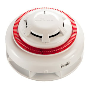
Apollo Series 65 Ionisation Smoke Detector w/ Flashing LED - 55000-216APO

SKU
55000-216APO
£0.00 £0.00
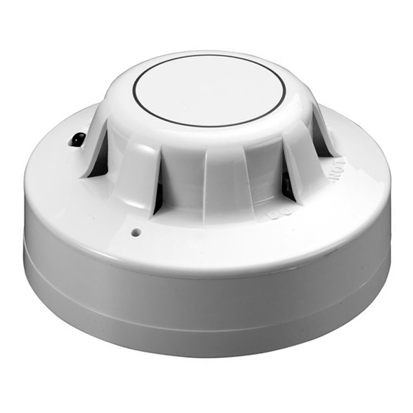
Apollo Series 65 Ionisation Smoke Detector with Flashing LED - 55000-216APO
Alternative Products
The Series 65 Ionisation Smoke Detector has a moulded self-extinguishing white polycarbonate case with wind resistant smoke inlets
Nickel plates stainless steel wiper contacts connect the detector to the base.
Inside the detector case a printed circuit board has the ionisation chamber mounted on one side and the signal processing electronics on the other.
The ionisation chamber consists of a reference chamber contained inside a smoke chamber. The outer smoke chamber has inlet apertures fitted with insect resistant mesh. The radioactive source holder and smoke chamber form positive and negative electrodes respectively.
An Americium 231 radioactive source mounted within the reference chamber irradiates the air in both chambers, producing positive and negative ions. A voltage across the electrodes produces an electric field.
Ions are attracted to the electrode of the opposite sign to their own charge. Many recombine but a small electric current flows between the electrodes. At the junction between reference and smoke chambers the sensing electrode converts variations in chamber current into voltage changes.
When smoke particles enter the ionisation chamber ions become attached to them with the result that the current flowing through the chambers decreases. This effect is greater in the smoke chamber than in the reference chamber, and the imbalance causes the sensing electrode to become more positive.
The voltage at the sensing electrode is fed to a comparator where it is compared with a factory-set clean air reference voltage. If the monitored voltage exceeds the reference voltage, the comparator switches the alarm latch on, increasing the current drawn from the supply from about 40μA to a maximum of 75mA. This fall in the impedance of the detector is recognised by the control panel as an alarm signal.
The alarm latch current also illuminates the detector integral LED. A remote indicator connected between the L1 IN terminal and the -R terminal will have a voltage equal to the supply voltage less 1 volt across it and so will illuminate.
To ensure correct operation of the detector the control panel must be arranged to supply a maximum of 33 volts DC and a minimum of 9 volts DC in normal operation.
The supply may fall to 6 volts DC in alarm conditions if a supply current of at least 10mA is available at this voltage. To ensure effective illumination of the integral LED and any remote indicator, the supply to the detector should exceed 12 volts.
To restore the detector to quiescent condition, it is necessary to expel any smoke and interrupt the electrical supply to the detector for a minimum of one second.
Mounting Bases are sold separately (click here to see compatible bases)
Watch the Video
| Key Features |
|---|
| > Includes Flashing LED: The integral LED flashes when the detector is in a quiescent state > Responds well to fast burning, flaming fires > Designed to operate in a variety of environments > Wide-operating voltage of 9–33 V DC > Wide-operating and storage temperature of -20°C to +60°C > Can be used on security systems > Electrically and mechanically compatible with Series 60 > Proven detection performance > Mounting Bases are sold separately (click here to see compatible bases) |
| Manufacturer | Apollo Fire Detectors |
|---|---|
| MPN | 55000-216APO |
| Colour | White |

Sort By:
No questions yet. Be the first to ask the question!
Specifications are given at 23°C and 50% relative humidity unless stated otherwise.
| Product Code: | 55000-216APO |
| Radioactive Isotope: | Americium 241 |
| Activity: | 33.3 k Bq, 0.9 μCi |
| Supply Wiring: | 2 wire monitored supply, polarity insensitive |
| Supply Voltage: | 9 to 33V DC |
| Ripple Voltage: | 2V peak to peak maximum at 0.1Hz to 100kHz |
| Quiescent Current: | 20-45μA at 24V |
| Switch-on Surge Current: | 110μA |
| Alarm Voltage: | 6 to 33V |
| Nominal Alarm Current: | 61mA at 28V, 52mA at 24V, 18mA at 10V |
| Alarm Indicator: | Red LED |
| Design Alarm Load: | 420Ω in series with a 2V drop |
| Holding Voltage: | 6V (min) |
| Holding Current: | 10mA (min) |
| Minimum Voltage Required to Illuminate Indicator | 12V |
| Alarm Reset Voltage: | 1V |
| Alarm Reset Time | 1 second |
| Remote Output Characteristics: | Remote is a current sink to the negative line limited to 17mA |
| Calibration: | Factory set to ∆V of 0.8V |
| Sensitivity: : | Nominal threshold Y value of 0.7 to EN 54-7:2000 |
| Temperature Range: | Max. continuous operating temperature: 60°C. Min. continuous operating temperature: 0°C. Min. operating temperature: -20°C (no condensation or icing). Storage: -30°C to +80°C |
| Temperature Compensation: | Automatic compensation by dual chambers to comply with EN 54-7:2000 across the operating temperature range |
| Humidity: | 0% to 95% relative humidity (no condensation) |
| Atmospheric Pressure: | Automatic compensation by dual chambers to maintain sensitivity up to a height of 2000m |
| Wind Speed: | 10m/s maximum |
| IP Rating: | 23D in accordance with BS EN 60529 |
| Dimensions: | 100 x 42 mm (100 x 50 mm in base) |
| Weight: | 102g (153g in base) |
| Materials: | White polycarbonate detector housing rated V-0 in accordance with UL 94, nickel-plated stainless steel terminals |
More from Apollo Fire Detectors