This website uses cookies to ensure you get the best experience on our website. Read our cookie policy


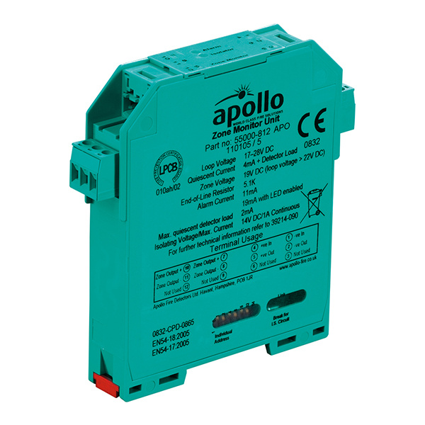
Apollo XP95 DIN-Rail Zone Monitor with Isolator - 55000-812APO

SKU
55000-812APO
£80.77 £67.31
Apollo XP95 DIN-Rail Zone Monitor with Isolator - 55000-812APO
- Buy 10 for £78.84 £65.70 each and save 2%
- Buy 20 for £78.22 £65.18 each and save 3%
- Buy 50 for £77.58 £64.65 each and save 4%
The Apollo DIN-Rail Zone Monitor with Isolator powers and controls a zone of up to 20 Apollo Series 65 or Orbis fire detectors in a Discovery or XP95 loop.
Electrical Description
The DIN–Rail Zone Monitor is loop powered and operates at 17–28V DC with protocol pulses of 5–9V.
Operation
The DIN–Rail Zone Monitor is factory preset to return an analogue value of 16 when all detectors on the zone are in the quiescent state and 64 when a detector changes to the alarm state. The unit latches in the alarm state.
A 5.1kΩ end-of-line resistor is used to monitor cables for open and short-circuit faults. Alternatively, an active end-of-line monitor may be used in conjunction with diode bases and a capacitor of up to 50μF fitted at the unit wiring terminals.
In either case an analogue value of 4 is transmitted during open or short-circuit faults.
The DIN–Rail Zone Monitor is fitted with a bi-directional short-circuit isolator and will be unaffected by loop short-circuits on either loop input or output.
For IS applications use DIN-Rail IS Zone Monitor, part number 55000-798.
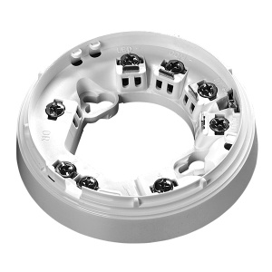
Mechanical Construction
The DIN–Rail Zone Monitor is supplied in a standard housing which is clipped onto a standard 35mm DIN rail (DIN 46277) using end stops part number 27447-528.
Connections are made via plug-in terminal blocks which accept wires up to 2.5mm².
Two LEDs are visible through the top cover of the enclosure.
The red LED illuminates in the event of an alarm condition being detected.
The yellow LED is illuminated whenever the built in isolator has sensed a short-circuit loop fault.
Device Addressing
The address of the DIN-Rail mounted zone monitor is set using the DIL switch. Segments 1-7 of the switch are set to 0 or 1, using a small screwdriver or similar tool. For the complete list of address settings refer to the Installation Guide (39214-090).
Backward Compatibility
The DIN–Rail Zone Monitor will operate only with control equipment using the Apollo XP95 or Discovery protocol.
Notes On Use
1. Zone voltage is regulated to 19V±1V for any loop voltage greater than 22V. If the loop voltage falls below 22V, the zone voltage is approximately 1.5V below the loop voltage. It is important to ensure that under worst-case conditions, the zone voltage is above the minimum operating voltage for the conventional detectors.
2. Alarm conditions are latched internally by the Zone Monitor. It is therefore necessary to reset the alarm even if non-latching conventional detectors are used.
3. To comply with BS5839: Part 1 response time requirements, manual call points can only be incorporated into zones connected by the Zone Monitor to XP95 systems if the control panel is programmed to recognise the alarm flag.
4. Manual call points can be located at any point in the zone wiring if active end-of-line monitoring with diode detector bases is used. If a 5.1 kΩ resistor is used for monitoring, manual call points must be connected between the Zone Monitor and the first detector.
5. The zone monitor includes a bi-directional isolator; therefore a single short-circuit on the loop wiring adjacent to the zone monitor will not affect the operation of the conventional detector zone.
| Key Features |
|---|
| > Loop-powered > Visible short-circuit and alarm LEDs > Built-in Isolator |
| Manufacturer | Apollo Fire Detectors |
|---|---|
| MPN | 55000-812APO |
Write Your Own Review

Sort By:
No questions yet. Be the first to ask the question!
More from Apollo Fire Detectors